FORGOT YOUR DETAILS?

CREATE ACCOUNT

Practical Skills

How to change the piezo igniter on a Jetboil Flash

9th November 2014

Disclaimer:The guide below is based on my own experience of performing this task. I am not an engineer, nor do I claim this to be an approved method of performing this task. Anybody following this guide does so at their own risk, and at risk of invalidating the warranty of their product/s

I love my Jetboil. I have both the Flash and the Sumo, and they are fantastic stoves – as long all you need is a simple way of boiling water or heating meal pouches quickly and for the cooking system to pack away into a small bundle. The only criticism I have is that the piezo push-igniter can be a little temperamental after extended use, and will probably stop working altogether eventually for most users. I got into the habit of carrying a ferrocerium rod or lighter around with me when carrying the Jetboil, which wasn’t ideal.

I eventually found a replacement piezo at the Cotswold Outdoor store in Betws y Coed. As always, I find the staff at this particular store extremely helpful and knowledgeable! Whilst working out how to replace the igniter unit I thought it would be worthwhile taking some photos and making this into a tutorial blog post…

A word of warning here – there are two type of spare igniter available for the Jetboil: the older type for the PCS/GCS and newer type for the Flash/Sumo/Zip etc. They look similar, but the one for the Flash has a flexible white wire instead of a stiff ceramic tube.

Step 1 – Disassemble Burner

The burner assembly has two main halves – a metal ring with attached burner, and plastic lower moulding with gas control valve and igniter housing.

Note the three plastic locating lugs, one of which is shaped differently, to act as a key when reassembling the two halves.

The burner (make sure it is cold and disconnected from gas canister!!) can be pushed down and rotated in an anti-clockwise direction (grip plastic housing securely). The burner will separate from the lower control valve (the connector is a little like a bayonet light bulb fitting)and then the plastic upper ring will come away from the lower plastic housing.

The white/grey wire will then hopefully slide out of the ceramic tube that runs through the burner unit.

Plastic lower housing and metal upper ring
Plastic mounting lugs and burner
Upper burner locating lug

Step 2 – Remove old igniter

The old igniter cable will probably be quite brittle, so take care. You may need the old cable to calculate the length of the replacement one.

The control valve is a friction-fit in the lower plastic housing, and should drop out with a gentle tap. If your burner unit is anything like mine then you will probably notice a lot of dust, sand and other crud in places it probably shouldn’t be. A few years of mountaineering, canoe and expedition adventures have taken their toll! I cleaned out the crevices with an air-blower I use for cleaning my camera lenses, but a gentle blow should do.
DO NOT USE ANY LUBRICANTS OR FLUIDS!!!

Comparing old and new igniters
Remove and clean gas control valve

Step 3 – Prepare and fit new igniter

The new igniter will have an insulating sheath all the way to the end, unlike the one you have just removed. I laid them side by side an calculated how much insulating sheath to remove. The sheathing can be removed carefully with a sharp knife, but be very careful not to nick or damage the wire underneath.
Fit the igniter module in the plastic housing, ensuring there is a positive ‘click’ from the two plastic retaining clips.

Locating new igniter in lower housing

Step 4 – Reassemble unit

Once you have stripped the wire, inserted the new igniter and cleaned out any crud then gently thread the wire up the ceramic tube in the burner.

 Insert the gas control valve back into the plastic housing and then line up the three plastic locating lugs on the upper metal ring. Finally, line up the burner on the control valve, press down gently and turn clockwise. The burner should push it slightly at one particular point, and then lock together. This took me a couple of attempts to get it located properly.
Finally, bend over the top 4mm or so of the exposed wire end so it just overhangs the edge of the ceramic tube. By bending the white wire as it exits the ceramic tube underneath you can make sure this doesn’t move around too much. Make sure no exposed parts of the wire touch any of the metal parts of the burner – the way it works relies on there being a gap between the end of the wire and the surface of the burner.

Locating new igniter in lower housing
Make sure there is a gap between burner and wire

Step 5 – Test ignite

If you now press the igniter you should see that familiar blue spark that shows it is working properly. Then attach a canister and test ignite.

 If you smell gas, hear anything unusual or cannot ignite despite there being a spark then stop, take it to a well-ventilated area and remove the canister (away from any other sources of ignition – gas canisters can have a habit of releasing gas after disconnecting them!). Then take the whole thing apart and see what went wrong!

Test ignite

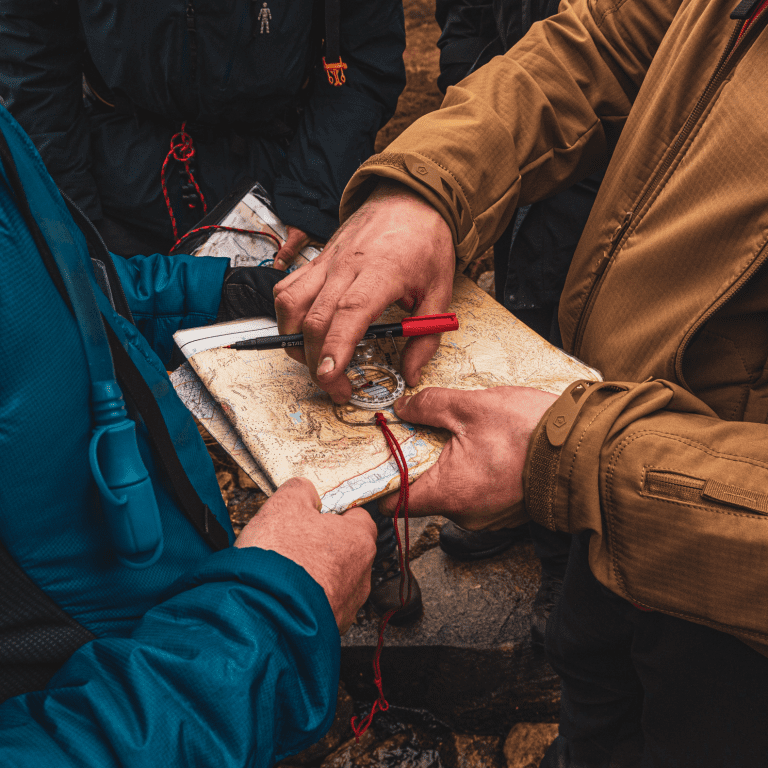
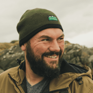
A Mountain Leader with over a decade of experience across the UK and overseas, Richard is our Lead Instructor and a partner in Original Outdoors. He is a specialist in temperate wilderness skills and the wild foods of the British Isles, and also works as a consultant for various brands and organisations. Richard lives in North Wales.

A Life more Wild.

A Life More Wild is the philosophy which underpins everything we do.

It encompasses practical skills, personal development, community learning and a journey to live more intentionally.

THE ACADEMY

EXCLUSIVE CONTENT AND TRAINING

.

TOP